Analyzing a simple RAID5
I am looking at a 4-disk RAID5 to illustrate the basic analysis steps in this example.
I originally used my Klennet RAID Viewer, but it is now discontinued.
However, the functionality is now integrated into Klennet Recovery
and is available in the evaluation version.
The task is quite simple:
- RAID level is known to be RAID5;
- number of disks is known, four disks;
- block size and start offset are not known;
- disk order is not known.
Finding block size and starting sector
This part of the problem is pretty straightforward.
You may want to look at the previous episode
of the RAID series if you need detailed explanations.

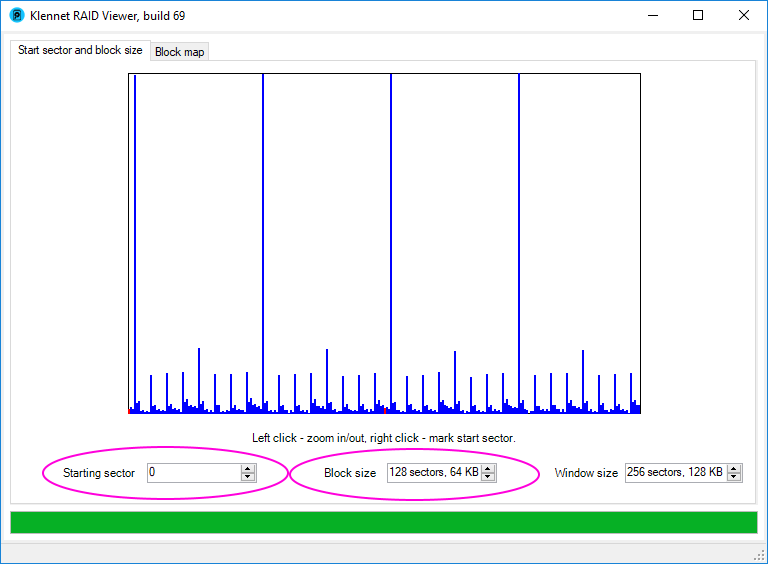
Default sector size view for a RAID5 sample
The default view is a bit cluttered, albeit showing a good signal-to-noise ratio.
First, drop the Window size parameter down several notches to reduce clutter.
The same chart at a smaller window size
With a smaller window size, the RAID block boundaries are clearly visible.
The next step is to work Starting sector and Block size to match computed block boundaries (red lines) to the actual block boundaries (highest blue lines).
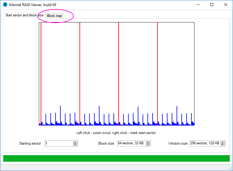
Correct start sector and block size settings
As block size and starting sector are set, switch to the block map view.
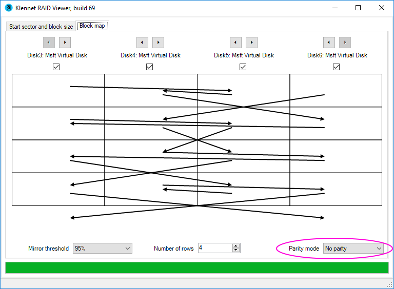
Default block map view
The initial block map is horrible, with pointers all over the place.
The first thing to do is to enable parity display.
The default setting is for a RAID0 with no parity.
RAID5 uses a single parity per disk (RAID6 uses two parities).
Switch Parity mode to One parity, and the picture becomes even more confusing.
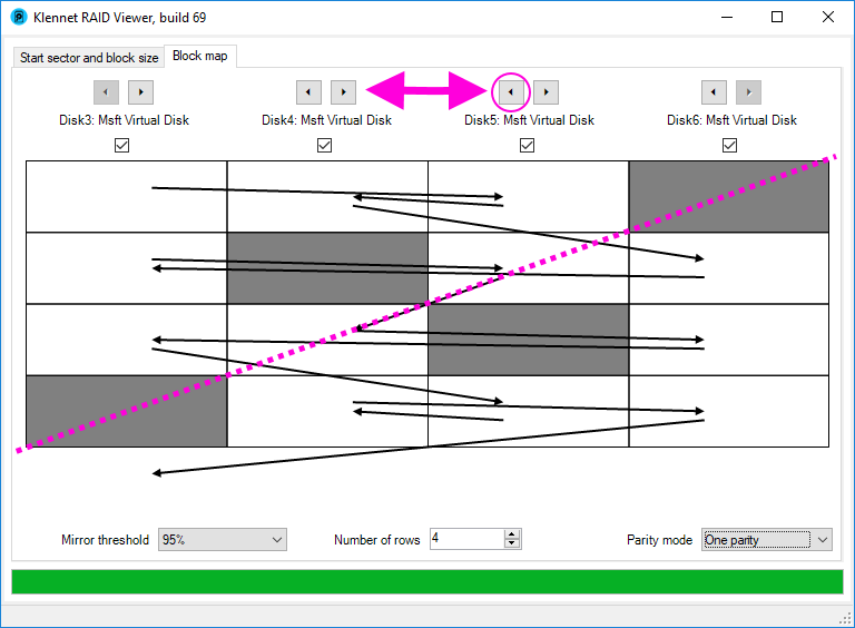
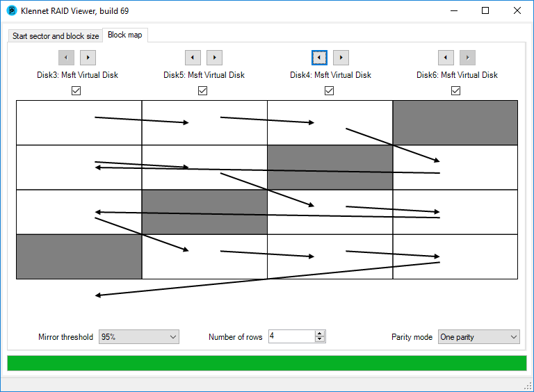
Block map view with parity highlight enabled
Once the parity display is enabled, the identified parity blocks are shown in dark gray.
Also, arrows going to and from the parity blocks are hidden,
as parity blocks are not involved in the arrangement of the data.
However, parity blocks themselves are arranged diagonally, most often from the top right to the bottom left (the diagonal is highlighted as the dotted line).
So, the first step is to arrange the parity blocks along the diagonal.
In this example, swap two disks in the middle using the arrow buttons at the top.
Final RAID5 block map
When this is done, the blocks are properly arranged.
You can confirm that by following the data ordering arrows.
This layout is "left-symmetric", used in most of the hardware RAID controllers,
and also typical for most Linux md-raid deployments.
The theoretical block map for a 4-disk left-symmetric RAID is shown below:
| Disk 1 | Disk 2 | Disk 3 | Disk 4 |
|---|
| 1 | 2 | 3 | P |
| 5 | 6 | P | 4 |
| 9 | P | 7 | 8 |
| P | 10 | 11 | 12 |
Note that in a symmetric layout, data blocks start after the parity rather than at the first disk in every row.
Filed under: RAID.
Created Tuesday, November 13, 2018