Concept
The disk imager reads the source media and creates a disk image file,
which holds a copy of all the readable content from the source media.
The imager does it in three passes with optional retries.
The goal of using multiple passes instead of a single pass is to capture all the easily readable data first,
then re-do the problematic parts and localize the media damage.
To this end, the imager uses a large block size on the first pass,
a smaller block size for the second pass, and then reads individual sectors on the final pass.
If, after three passes, there are still bad sectors, the imager will retry the bad sectors if configured to do so.
Output formats
Raw image
Raw disk image is a simple byte-for-byte copy of the source media.
- Sometimes also called dd image.
- Resulting disk image file size is the same as the source media size.
- Can be read by all available data recovery tools.
- Can be mounted on Windows using a free version of Arsenal Image Mounter (as of April 2026).
- Can be mounted on Linux using a loop device.
VHD and VHDX
These are virtual hard disk formats by Microsoft.
- VHD format has a 2 TB size limit.
- Can't be opened by many data recovery tools.
- Can be mounted on Windows using Disk Management.
- Can be mounted inside a Hyper-V virtual machine.
Controls and settings
Start
Adjust the settings before starting the process.
Once you have configured the settings as you see fit,
click Start.
Later, you can pause and resume any time you like.
Pause
You can pause and resume the process whenever you like.
However, do not disconnect either source or target.
You can adjust the settings while the process is paused.
Stop
The Stop button stops the imaging.
The resulting disk image file contains the data read before you stopped the process.
Block sizes and timeouts
This group of settings controls parameters for each pass.
The block of the specified size is read in one request.
If the read fails within the set timeout, the block is queued for the next pass.
During the next pass, the same (larger) block is re-read in smaller blocks with their own timeout settings.
This repeats until the retry limit is reached.
- The third and subsequent retry passes (if any) always use single-sector blocks.
- The default values are reasonably good, so there is really no need to change them.
- Somewhat surprisingly, the same settings work for both SSDs and mechanical hard drives.
If there are many bad blocks for your given first pass settings, consider decreasing the block size for the first pass.
This will reduce the number of time spent in subsequent passes, reducing the overall imaging time.
Retries
This setting controls how the imager treats final bad blocks.
When set for "No retries", the imager declares the blocks bad, and that's the end of it.
You can configure the imager to retry all the bad blocks.
It will then stop after one, two, or three consecutive unsuccessful passes (during which none of the bad blocks was successfully read)
or continuously retry until you stop the process.
Be careful with the continuous retries mode.
Depending on the device you are imaging and the damage, continuously trying to read bad spots may further damage the device.
Bad block fill
This group of settings determines what is written to the image file when the corresponding sector of the source is unreadable.
Consider using a text signature - it allows you to find damaged spots later by doing a full-text search for the signature in the recovered files.
The imager fills the entire bad sector with zeros or a pattern you specify (by repeating the pattern to the end of the sector).
Supported options are:
- zeros;
- ASCII text pattern;
- single byte fill (specify two hexadecimal digits).
Map and timing display
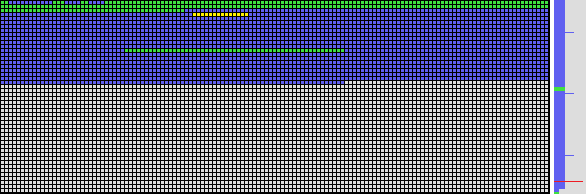 Disk imager map and timeline display.
Map colors
- Gray - not yet processed.
- Green - read successfully.
- Blue - read successfully; the data was either all zeros or all 0xFF (typically indicates an empty space).
- Yellow - read failed, queued for re-analysis in smaller blocks.
- Red - read failed.
Read time indicator
The vertical band on the right side displays the time spent reading each block relative to the timeout.
An empty line indicates plenty of time to spare, and a full line means the request is close to the set timeout.
The coloring is the same as above, with one exception - no yellow.
All the read failures are displayed in red.
For optimal performance, keep the right half mostly free by increasing timeout (see examples below).
Read timeout display examples.
| Good |
|
Increase timeout if possible |
 |
 |
 |
 |
 |
|
 |
 |
 |
 |
 |
Parallel imaging
Technically, Klennet Recovery can image multiple disks in parallel.
In practice, do not do that.
Even if you arrange imaging from multiple source disks to multiple target disks
so that no two writes go to the same target disk, you still should not do that.
If there is a problem with one of the source disks, the controller or even the entire system may lock up
until the disk built-in error recovery is complete.
The lock-up affects all the drives on the same controller or all the drives in the system.
The interactions between multiple disks are likely to cause the imager to attempt to reset multiple drives in turn,
leading to a long series of timeout-recovery cycles.
More information
For more information, please refer to
Next step
Once the imaging is done, open the resulting disk image file by using Open toolbar button.
You can then work with the disk image file as if it were a physical disk.
Refer to Physical disk list tab for information.